 Real Time Kinematic (RTK) GPS surveying is great, but one of the biggest challenges in the field is having sufficient UHF radio range between the base and rover. In this two-part article, I’ll show you how to improve that range substantially with the equipment you probably already own, give you recommendations of a few cost-effective additions that also make a big difference and end in Part Two with several case studies I’ve done with these techniques. A balancing act on just about every job is having sufficient survey control for the GPS base station and having radio coverage between the base and rover. Control surveys and control points aren’t free, so getting as much range as possible can be especially important. Also, having field adaptable methods and a few extra “radio” tools in your tool kit can save the day and mean the difference between finishing a job and having to reschedule another site visit.
Radio Range, the basics.
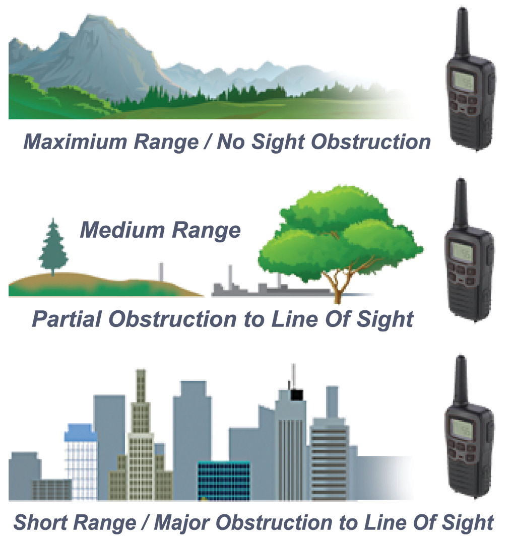
Radio range is highly dependent on site conditions. The further you can see, the more range you typically will have.
Radio range is subject to a lot of site conditions. Basically, the more stuff in the way, the less radio range you’ll have. If you’re base is on top of a mountain looking out over the water to a rover on a boat in the distance, you’ll get dozens of miles of coverage with the same radio that will struggle to go just a mile back in the urban canyons of a major city.
 The differences between these two extremes is not only the unobstructed view in one area versus the other, but also the extra ‘noise’ present in a highly urbanized setting. Picture a major league sports stadium. You’re on the field and your friend is up in the nosebleed seats. If you’re the only two people in there and there’s no air conditioning running, no sound from the crowd, and no other noises, you can practically have a conversation with each other even though you’re hundreds of feet apart. Now, if there is a playoff game going, the stadium is packed and you’re sitting right next to each other, you probably have to shout just to hear each other at all.
Radio range can be dramatically impacted by the environment it is operating in, and adding more height and more power (like sitting in the nose bleed section and screaming your head off) won’t necessarily have any beneficial difference to a lack of radio range.
The general examples I give for radio range in this article are for the middle of the road type job. It’s not the best-case scenario of totally open country, the lone mountain by the sea with nothing but you and your lone survey boat for as far as the eye can see, and it’s not the center of Manhattan either with about 1000 sources of interference. If you’re working standard ‘rural America’ these estimates probably are about right.
Antenna Types and What they do.
 There are dozens of antenna option out there but the three antennas we will look at in this article are the rubber duck, the whip, and the Yagi. The rubber duck is the most common ones you will get as part of the original equipment when buying an RTK receive. The whip is the most common equipment upgrade at your local survey shop. The Yagi may not be at your local survey shop, but is common in the radio world and pretty easy to find using a Google search. There are a few on-line survey cable dealers also that I’ve seen who stock this as well.
They all have strength and weakness. In a nutshell, the rubber duck is great for being compact and not getting caught in every bush as you walk by but does limit radio reception. These are the compact antennas that are usually about six inches long and look like a plastic-coated black cylinder about as big as a marker pen. It is ideal for a rover, but probably not the best for anything else like a base or a repeater, unless you’re not going far at all (like under a mile).
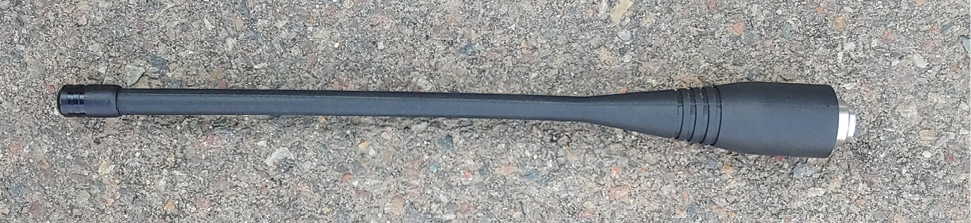
Three antennas discussed in this article are the rubber duck (above), whip (middle), and yagi (bottom).
Pictured to the right is a rubber duck. It is designed to fit in the bottom of the receiver and not cause strain on the connector. This is the best tool for a rover antenna because it can handle being moved around and is small enough that it doesn’t get caught in every low hanging branch that comes along. All my recommendations are to exclusively use this kind of antenna on the rover. Using external antennas for the rover runs a very real risk of damaging the connector on the receiver. It’s also not as effective as other suggestions I’ll make in Part Two of this article.
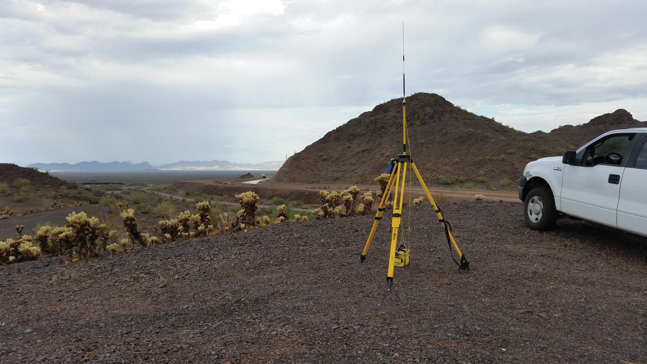
 The whip, or ‘high gain’ antenna (measured in decibels and usually having a value around 5dB) is longer, thinner, and usually all metal with either a big base and\or a few thicker cylinders or coils in the middle. They also need a separate mounting point because they do not thread directly to a GPS receiver. Most of the time you should put it on its own tripod and range poles. You will also need a connecting cable and not directly connect it to the antenna port on most integrated receiver\antennas used at a GPS base. This is a big disadvantage for a rover, but usually not much of a burden when talking about a typical base or repeater setup. The biggest advantage of a whip is it provides much better electronic sensitivity when compared to a rubber duck and can increase the range of radio transmission\reception by 2 – 10 times when compared to the rubber duck. It’s like getting free energy just by focusing the radio energy better.
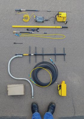
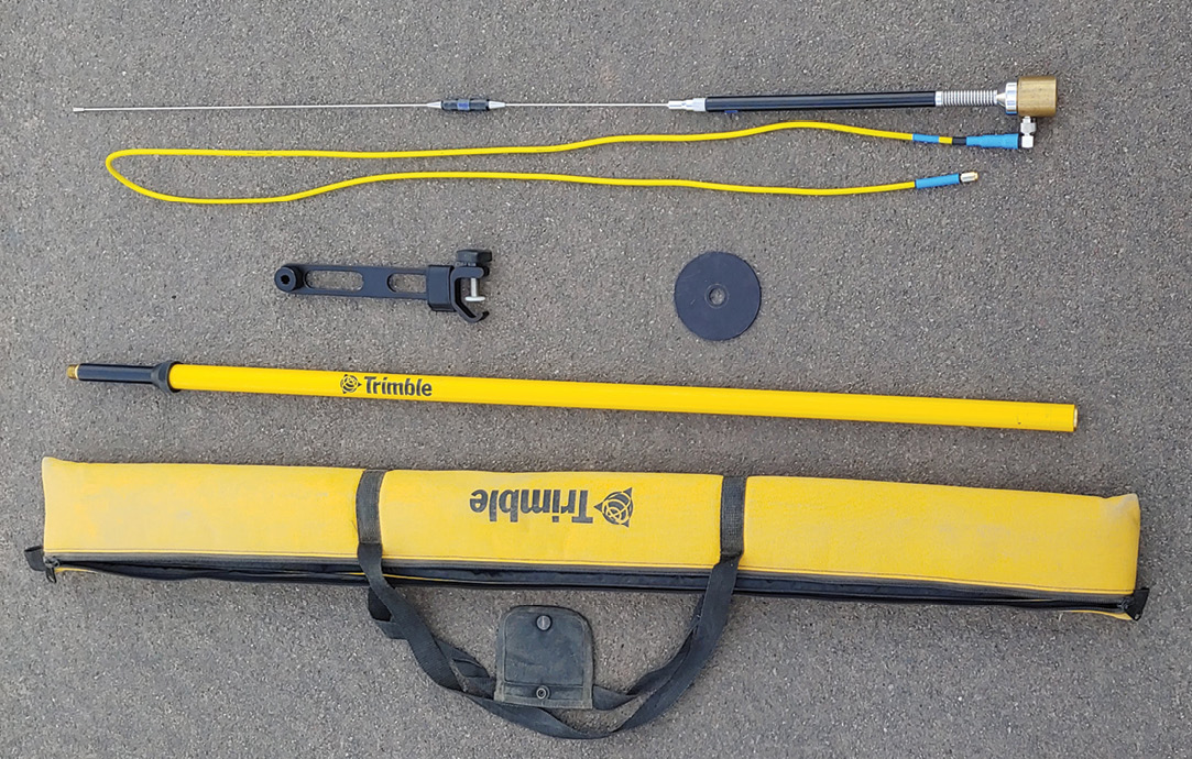
In the picture above is a whip antenna with a threaded base (5/8”x11 for the standard survey range pole); a short five foot cable (explained in the next section about cables); an extension pole to get a little more height (also explained in the last section about antenna height); a disk to connect the antenna or pole to the top of a standard tripod; a clamp mount to connect the antenna to a range pole directly (SECO Part Number 2133-03); a convenient bag to store all of the equipment.
 The last antenna featured is the Yagi. I always think of the Fred Flintstone antenna or an old rooftop TV antenna with all the cross arms going everywhere. Instead of a single ‘stick’ sticking up like the rubber duck or the whip, this is a cross bar with a bunch of perpendicular cross arms. The disadvantage is it’s big, takes a more complicated mounting system and also needs to be pointed in a particular direction correctly. This antenna has fairly well pronounced blind spots, so pointing in the wrong direction can actually limit your range. So why would you want to use such a thing? Simple, in the correct direction it works miracles and can extend your range incredibly. This is the go-to tool when you want to reach that distant mountain top radio repeater. The gain on an antenna like this usually is 9dB.
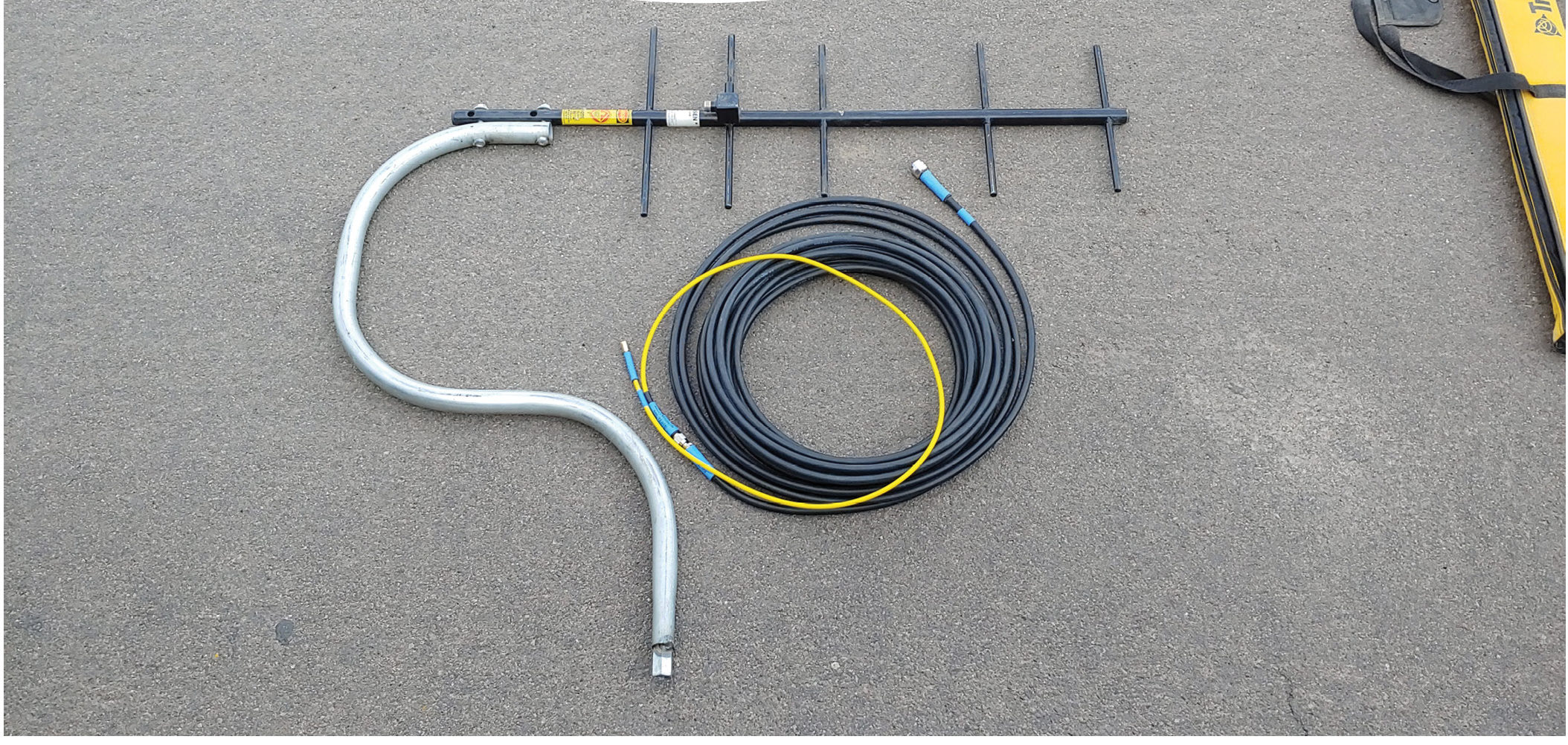
Pictured above is a 9dB Yagi mounted to a piece of 1 inch conduit. The conduit is bent so the center of gravity is in line with the vertical axis of the pole it is mounted to. This keeps the antenna from wanting to tip over and makes plugging it into the top of a tripod easier. At the bottom of the conduit is a 5/8”x11 threaded coupler nut. It is spot welded in and makes it easy to attach to any standard survey range poles. The longer of the two antenna cords I had fabricated is in two parts. The short 5-foot yellow part has an SMA connector end for attaching to the antenna port of the GPS receiver. Note, SMA connectors can’t attach to cables that are physically large in size, so this is basically required to have some form of adapter. It is possible to use an adapter about an inch long the goes from TNC to SMA. I recommend against this however because the stiffness of the thicker wire can put strain on the antenna port on the bottom of the GPS receiver, so it is usually better to use a jumper wire. Having the flexible wire also makes attaching the cable to the GPS a lot easier.
The other end of the yellow jumper wire is a TNC and is the same as the antenna ports I have at the base of many of the 5dB whip antennas. This is done to try to make as many things standard and interchangeable as possible. If one cord breaks in the field, chances are you can substitute something from another kit of equipment. Lastly is the 50-foot coil of LMR-400 (low loss) coax cable. It is 50 feet long and falls right in the Goldilocks zone for most setups I’ve done (not too long, not too short). The connector at the antenna end is an N-type. This is typically the most common connector I’ve seen, but double check your antenna after you purchase it to make sure you’re getting the correct end on your cable.
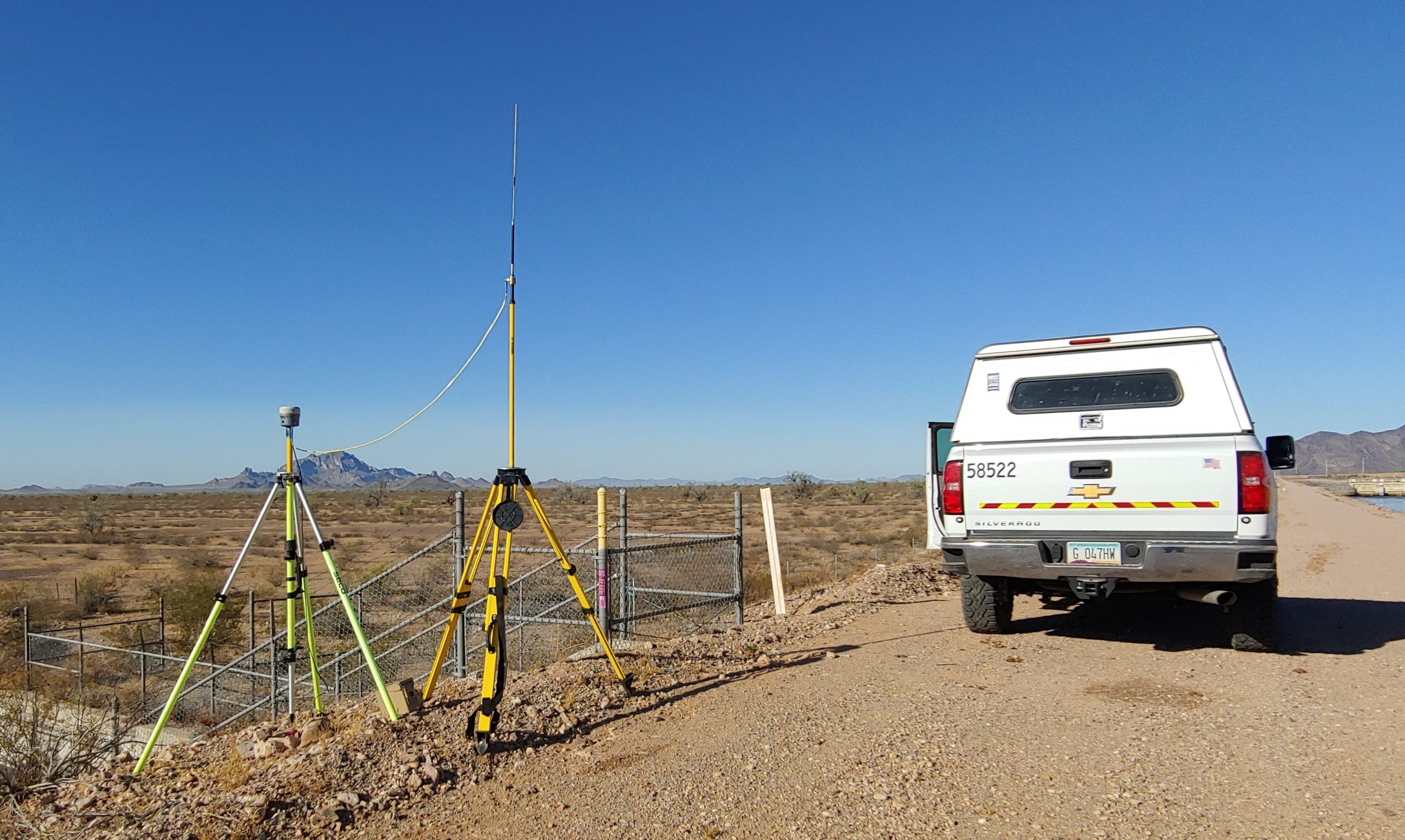
Polarization, the “what’s up” in the world of radio
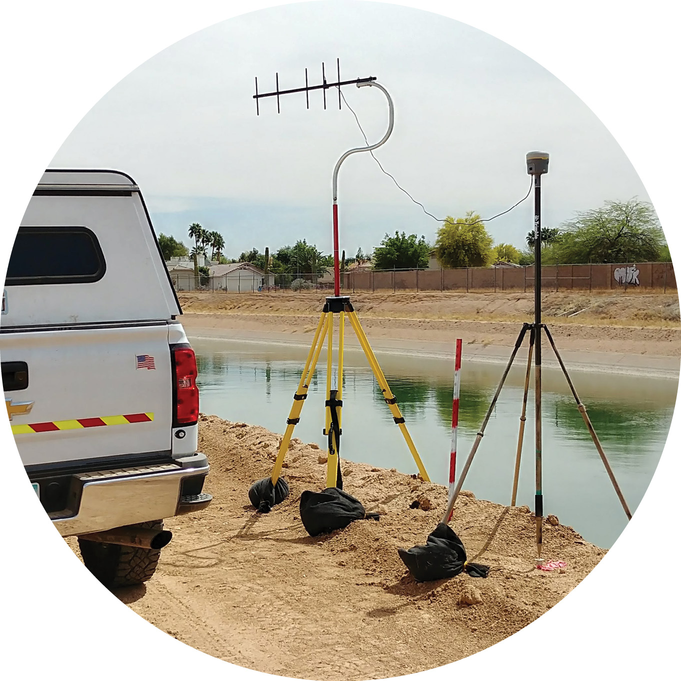
A base with an external yagi antenna.
I’m trying not to use too many complicated radio terms in this article, but there is a quick note about how antennas work worth mentioning. Antennas create a field of radio energy. This field isn’t the same everywhere, so there are “blind spots”. Polarization is a fancy term that you can simply think of as making everything parallel so it works. All your antennas should stick up strait and be ‘plumb’. On the rubber duck and the whip, that’s easy, the antenna is a stick and you hold it plumb. On the Yagi, all the cross arms are the parts that are plumb. Just look in the pictures that are in this article and you’ll see what I mean.
Antenna cables, the make-or-break link in the system
To use an external antenna you must have a cable. Coaxial cable is the most common thing you will see. It looks like a single round wire. Inside it is a solid coper wire surrounded by an insulator and a metal braded wire tube all nestled in a final outer protective sleeve. Not to get overly technical, but the smaller the wire, the easier it is to use, but the less it will work in the long run (pun intended). You want the cable to be only as long as you absolutely need it to be because it will lose energy with every extra foot of length. There is no point adding a better antenna to your system if you are only going to lose all that advantage with energy loss in the cable being used to connect everything together. Sounds like an easy fix to just use a better cable, but that has some disadvantages as well. Better in this case means bigger and also stiffer. To have a cable with very low loss ends up with a wire that looks (and feels) more like a frozen garden hose than a flexible extension cord. On the professional tower installations that mount antennas a hundred feet or more up the tower from their radio equipment these cables can reach an inch or so in diameter. This is completely impractical for field use by a survey crew with what usually is a temporary installation. The longest cable I use is 50 feet long and it is only for the Yagi I have. It’s also about the diameter of your pinky finger (LMR-400) and not very easy to deploy. All the other cables I use are 5 – 6 feet long and are the 1/4-inch diameter flexible kind. They have higher loss, but aren’t long enough to have sufficient total loss so work fine. The next bullet point we’ll talk about antenna height tradeoffs.
Antenna height.
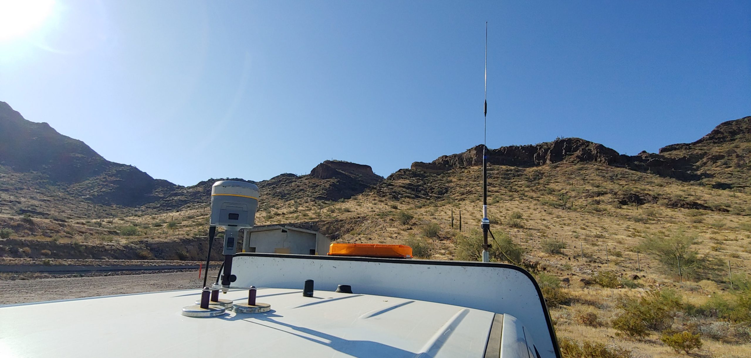
A stand alone radio repeater strategically positioned on a high point. In part two of this article we will fully discuss this kind of setup.
There is a simple reason a lookout tower is up high. You can see farther. Same is mostly true for your antenna, but a taller antenna also means a longer cable, so the tradeoff balances out a lot faster than you might think. As I mentioned in the section above, smaller flexible antenna cables also have a lot more loss. Having a 25-foot-long cable that is thin as a pencil might just negate all the gain you get from a better antenna and leave you doing a more complicated setup with nothing to show for it on the bottom line once all the gains and losses are added up (gain for an antenna and loss for the cable).
Tall temporary structures can also be safety concerns. Putting an antenna of any weight up high in the air acts as a lever wanting to bend in the slightest breeze and blow back down to the ground. At best you’ll damage your antenna, range poles and tripod, if it blows over in the wind and at worst, you’ll do a lot more damage by falling on people or other equipment (survey truck, the base station, etc.). Heights over 14 feet also bring you within range of many power lines. This is a very real danger. Think! You are extending a metal antenna connected by a wire up to where a power line is. Remember that TV show, the weakest link? That will be you if you become the path to ground for the high voltage wire overhead!
My advice is to keep temporary antenna heights below about 12 feet (that’s an antenna on two 4-foot range pole sections, or an antenna on the top of your survey truck). You’ll use shorter cables which is good. You’ll avoid things blowing over in the wind and you’ll avoid the dangers of overhead power lines.
As we will see later in this article, converting an external radio connected directly to a GPS base into a remote repeater gives you many more favorable equipment setup options. You can put a repeater on top of a hill or tall building and be far more effective than just raising the antenna on a connected external radio vertically into the sky.
So now that we have a few of the basics defined and out of the way, let’s look at the most common configurations of base rover combinations.
Level 0, Basic Setup with a Base & Rover, using internal radios.
The simplest base setup uses the internal radio of the base and rover. It’s easy, has the fewest extra parts, but can limit the radio range substantially, usually limited to a mile or so.
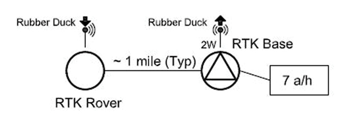
Level 1, an upgrade: Base & Rover with external radio at base.
Probably the most common upgrade I’ve seen is to pair the base with an external radio to increase the range. This is done by using a ‘Y’ cable that both powers the GPS and the radio, and provides a serial data link from the base to the radio. It’s easy to configure (this is typically done by the vendor not your field crew) and gives a nice ‘brute force’ solution that extends the range out to a few miles. Most of the time the external radio is also set to its highest power setting and you’re off to the races with a few more miles of coverage.
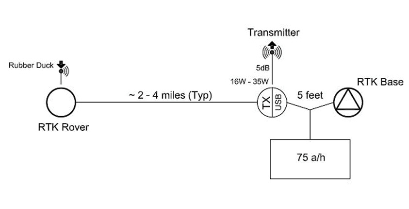
Is using a high wattage external radio connected by a wire to the base the best use of the equipment? In a lot of ways no.
 Let’s look at each piece of the puzzle a little closer. First, we’ve changed the transmitting antenna at the base from the rubber duck that threads directly into the receiver to a better 5 dB gain whip antenna; second, we’ve heightened the antenna a little higher (when compared to the height of an antenna connected to the GPS receiver); lastly, we’ve increased the transmitting power. So, what benefit did each change really give us? In my experience, the most benefit comes from changing the antenna at the base. I’ve had experience with getting near equal range from just putting an external 5 dB gain whip directly connected to the base via a short cable and using the internal 2-watt radio as I do with having a 35-watt external radio. If there is something that blocks your signal downrange, like a big mountain or valley edge, it almost doesn’t matter how much power you throw at the problem, you still have a ‘radio shadow’. Think of it like trying to shine the beam of a flashlight around a corner. It doesn’t work. Using a spotlight instead doesn’t solve the problem either, it just uses more power to fail in the same way.
Level 1 conclusion
The cost: We added an external radio and a 5dB whip antenna to our inventory
The return on investment: We gained a few miles of range, but still have limitations because our radio transmitter is forced to be at our base location. If the base is in a valley or other bad radio spot, our radio range is limited.
In part two of this article, we’ll unpack how to set up your equipment differently and get a lot more range. ◾
Brian Fisher is a professional land surveyor in Arizona. He is also the volunteer Arizona State Geodetic Coordinator for the National Geodetic Survey.