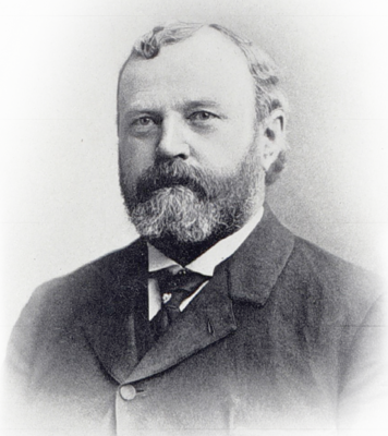
 A critical aspect of a triangulation network was to establish a baseline that was accurately measured upon the ground. During the late 1800’s, the U. S. Coast & Geodetic Survey began experimenting with several measuring devices that would assure precision measurement. Out of this experiment came a pair of identical tube-shaped devices that became known as the Duplex bars which collectively went on to become one of the most accurate surveying instrument ever developed.
The concept was invented by William C. Eimbeck in 1885, but the Duplex bars were initially met with little consideration and no action was taken for their development or use in the field. Two years later, an invitation was internally issued by USC&GS for the design of additional apparatuses for use on measuring baselines. Eimbeck resubmitted his Duplex bar design with the suggestion they be brought before expert geodesists for both their consideration and criticism. This resulted in several comprehensive letters being received from the leading geodesists within the agency. There were no critical remarks given forth as to the functionality of the bars, but they still needed to be field tested. The main concern was whether the Duplex bars could maintain equality in the mean temperatures of their components. Approval was soon forthcoming to at least give them a try and test their worthiness. In 1890, after a thorough review of its merits, Dr. Thomas C. Mendenhall, then superintendent, authorized the construction of the Duplex bars.
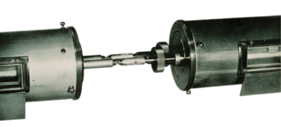
The contact points of the Duplex bars were tipped with agates. Windows in the sides of the bars allowed for the reading of the scales during precise measurement. Courtesy of NGS.
The full plans and specifications for the Duplex bars were provided by Eimbeck for their manufacture. The apparatus was built within the USC&GS instrument shop by chief mechanician E. G. Fischer whose ingenuity, skill, and personal interest in the project truly made the working model a complete success. The construction process was painstakingly slow with every detail having to first pass inspection by the Instrument Board of the agency before final authorization. Finally, in the spring of 1893, the bars were completed and placed on exhibition at the World’s Columbian Exposition at Chicago. The Duplex bars, however, gained little attention since they had no fancy features and merely resembled stationary tubes. Mention of the Duplex bars was not published in the exposition’s guide book that detailed a collection of other instruments, so those attending were not alerted to look for them. A large plaster replica of the earth’s surface displayed at the Coast & Geodetic Survey’s area was the center of attraction and likely drew any stray attention away from the bars.
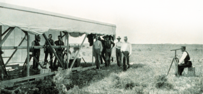
Aligning the tips of the brass and steel rods of the initial Duplex bar over the baseline starting point while under the shelter sled. Courtesy of NGS.
After nearly a decade from its initial concept, the Duplex bars were presented at the Geodetic Conference in January of 1894. At this conference, the measuring device finally gained its deserved attention and was recommended to be put to immediate use in the field on a baseline as soon as practicable.
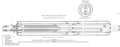
The main components of each Duplex bar were two inner tubular rods spaced 2.80 centimeters apart. One rod was constructed of steel and the other of brass so the effect of measurement could be determined by using two separate metals. The remaining parts of the device were made entirely of brass that was nickel-plated to insure equal power for the absorption and emission of heat. The outside of the tubes were covered with a felt sleeve which further detracted from any special notice.
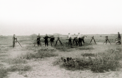
The measuring of a baseline is underway with the Duplex bars on two sets of trestles while the third set is being readied for the leapfrog of the rear bar. Courtesy of NGS.
The reason for the bimetallic construction of the two inner rods was to show the relative displacement or shift with respect to one another during measurements when effected by temperature changes. This resolved the problem of thermal expansion which was crucial during the measurements of the baselines in precise triangulation networks. A shift would not be noticeable or able to be considered without utilizing two different types of metals. Both the steel and brass rods were judged to be sufficiently sensitive.
Each Duplex bar weighed 118 pounds which made them light enough to easily handle, yet heavy enough to remain stable during measurements. The basic length of each bar was exactly 5 meters, notwithstanding the excess or deficiency determined at the points of contact where the measurements were made. Each bar contained three symmetrically disposed thermometers to determine the coefficients of expansion. The shifts, or relative displacements of the inner components, were determined by successive readings of bar scales that were located at the front and rear ends of the bars. Removable brass end caps protected the end points when not in use.
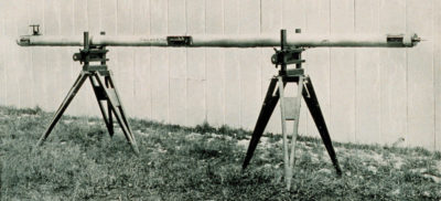
One Duplex bar on a set of trestles that supported it and also also adjusted it for level and height. A telescope on one end aligned the second bar with the first one. Courtesy of NGS.
The precise length of each Duplex bar was related to the international prototype meter, No. 21, which had been standardized by comparisons upon the 50-meter comparator base at USC&GS while using the 5-meter standard bar No. 17 in melting ice. Bar No. 17 was one of the more ingenious designs for a baseline measuring apparatus and was developed by Robert S. Woodward in 1890. The “Ice Bar”, as it was known, consisted of a bar continuously surrounded by ice as it measured. (See The American Surveyor, April 2007). Eimbeck’s design of the Duplex bars, however, eliminated the need to use the often cumbersome Ice Bar that required a special trough on rails and a continuous supply of ice.
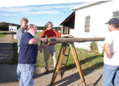
Examining a more than century-old Duplex bar in 2004 are NGS employees (right to left) Steve Breidenbach, Audie Murry, Kendall Fancher and historian John Collins. Courtesy of David Doyle.
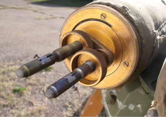
Each Duplex bar was supported on two special tripods when used together were called trestles. To begin a measurement, the first bar was placed upon its trestles, roughly aligned, and rotated so the end components were in the “face up” position. The contacts were made by bringing the tips of the components, called “knives”, to the ends of the adjacent bar “brass to brass” and “steel to steel”. The ends of the knives were tipped with agate stones. Next, the contact slides were set to zero and the knives set normal to each other by use of a sector transit. The rear end of the initial bar was then accurately aligned over the ground point with the sector transit so its steel and brass components fell vertically over the beginning ground mark and lined up in the direction of measurement. The thermometers, inclination sector, and bar scale were then read to complete the first bar.
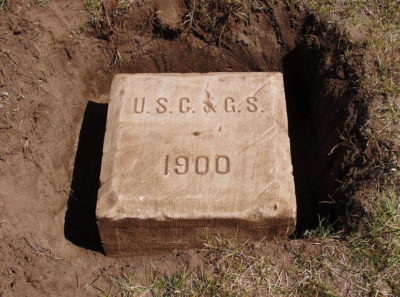
A large stone block with a copper bolt in the center marks the northeast end of the Page (Nebraska) Base Line that was measured with the Duplex bars in 1900 during the 98th Meridian Survey. Courtesy Jerry Penry.
The second bar was placed upon its trestles and roughly aligned. The components were rotated “face up” and the bar was slid back to approximately come in contact with the front end of the first bar both horizontally and vertically. The entire second bar was aligned with a telescope that was resting on the first bar while sighting a distant point on the line to be measured. The final contact of the agate-tipped knives on the front of the first bar were brought together to the agate-tipped knives on the rear of the second bar by adjusting the contact screws. Contacts of the tips were made with the use of microscopes. The thermometers, inclination sectors, and bar scales were then read to complete the laying of the second bar. Approximately 10 meters was now measured on the line.
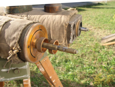
The ends of a Duplex bar showing the agate-tipped “knives” where the contact points were made during measurement. The rectangular-shaped bar in the top photo next to the Duplex bar is believed to be the Secondary bar which was another baseline measuring apparatus developed by USC&GS. Both photos courtesy David Doyle.
The first bar was then brought forward, placed on a third set of trestles, and then slid back to the front end of the second bar in the same manner. The first set of trestles were brought forward each time and readied for the rear bar to come forward. This leapfrog process was repeated one bar or 5 meters at a time until the section of the baseline had been completely measured in both directions. The first measurement of the line was made in the morning hours under rising temperature and the second measurement was made in the afternoon hours under falling temperature. The bars were given the designations Bar No. 15 and No. 16 to distinguish them from the other measuring devices of USC&GS.
 The initial field test of the Duplex bars came in September of 1897 when the Salt Lake Baseline was measured. The crew consisted of 15 men each having a specific duty. Eimbeck was chief of the party and made the contact readings and read the scales. As the bars were moved along, and the trestles were brought forward with each new measurement, the men worked under a canvas tent. This tent was 56 feet long, 12 feet wide, and 9 feet tall at the center of the ridge line of the arched roof. The tent was attached to two wooden runners on the sides that rested on the ground. The ends of the tent were always kept open and the side flaps adjusted to keep direct sunlight off the bars and to also keep wind from striking the bars. Air was kept circulating throughout the tent by adjusting the side flaps. The entire tent system was called the shelter sled and was pulled forward by two horses.
 In 1900, the Duplex bars were used on measuring sections on nine different baselines of the 98th Meridian Survey in the center of the United States. Baselines were located at Alice, Seguin, Lampasas, Stephenville, and Bowie in Texas; El Reno, Oklahoma; Anthony, Kansas; and Shelton and Page, Nebraska. Within a few years, Invar steel tapes were wholly used on the baselines due to the speed and accuracy in which they could be utilized.
Eimbeck considered his creation one of simplicity, yet only the concept held to that notion since the Duplex bars were one of the most accurate measuring devices ever developed. Born in Brunswisk, Germany, Eimbeck came to the United States and settled near St. Louis where he became a civil engineer. He worked on the construction of the famed Eads Bridge and also worked in the St. Louis city and county offices. He gained employment with USC&GS on July 1, 1871, and was initially assigned to the transcontinental triangulation crews working their way along the 39th Parallel across Missouri and Kansas. He later performed astronomical and triangulation duties in many areas of the country. His death on March 27, 1909, brought sadness to the agency to which he was fully devoted. He is buried at New Haven, Missouri, a small town west of St. Louis. Above the top edge of his tombstone are the letters USC&GS.